UDMpc
1, 2 drives, 24-48V, up to 10/20A
EtherCAT ® Single & Dual Axis Drive Module
- Universal single and dual axis Drive Modules for EtherCAT networks
- 24Vdc to 48Vdc, up to 10A continuous and 20A peak current (400W/800W)
- Digital control for easy setup and diagnostics
- Supports AC Servo / DC brushless, DC Brush, voice coils and closed and open loop step motors
- Dual loop with dual feedback per each axis
- 20kHz sampling and update rate of all control loops
- Digital I/O: 10 inputs, 6 outputs
Analog I/O: 4 inputs, 2 outputs, 12 bit resolution
- Safe Torque Off (STO)
|
 |
|
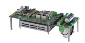
The UDMPC is a line of EtherCAT universal single and dual axis drives for AC servo /DC Brushless, DC brush, two- and three-phase step motors. The module is designed to be mounted on a carrier board.
The UDMPC operates as an EtherCAT slave under any SPiiPlus EtherCAT master Controller including the PC based SPiiPlusSC Soft Controller. It is designed to address high performance applications with demanding move & settle, smooth velocity and stand still jitter requirements with power of up to 400W/800W (continuos/peak) per axis.
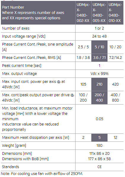
The UDMPC is offered with the following current levels: 2.5A/5A (cont./peak), 5A/10A and 10A/20A.
Optional Safe Torque Off (STO) module cuts the power to the motor without removal of the power source to comply with SIL-3 and PLe safety levels.
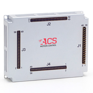
The module can be provided with the optional UDMpc-2-048-BOB BreakOut carrier Board and a set of mating connectors.
This carrier board also enables the user to configure the safety and general purpose inputs and outputs (5V, 24V, sink or source); test the STO operation
and set the network ID of the unit.
Servo
A standard comprehensive set of powerful algorithms to enhance accuracy, move & settle time,
smooth velocity, stability and robustness.
• Advanced PIV cascaded structure • Loop shaping filters • Gain Scheduling
• Gantry MIMO control • Dual feedback / loop control • Disturbance rejection control
Optional Servoboost® algorithem that provides better, more consistent servo performance,
insensitive to noise and large changes in the system.
Drives
The model can simultaneously drive all axes at a current level of 1A.
When operating with an optional cooling fan, part number FA-1608K-100/LF, the model can drive three axes at a current level of 3A.
Supply
The module is fed by two power sources. A motor supply and a 24Vdc control supply. During
emergency conditions there is no need to remove the 24Vdc control supply.
Motor Supply
Range: 24Vdc to 48Vdc
Current rating should be calculated based on actual load.
Control supply
Range: 24Vdc ± 10%
Maximum input power: 15W
Input current: <0.6A
Motor Type
Two- and three-phase permanent magnet synchronous (DC brushless/AC servo), DC brush, Voice coil, Two- and three-phase stepper (micro-stepping open or closed loop).
Feedback
Types: incremental digital encoders, optional: Sin-Cos encoders, Resolver, absolute encoders
Incremental Digital Encoder: Four, two per axis, A&B,I; Clk/Dir,I
Type: RS-422.
Max. rate: 50 million encoder counts/sec.
Protection: Encoder error, not connected
Sin-Cos Analog Encoder (optional): Two, one per axis. Type: 1Vptp, differential.
Programmable multiplication factor: x4, to x4,096
Maximum frequency: 250kHz
Automatic compensation of Offset, Phase and Amplitude
Maximum acceleration with Sin-Cos encoder: 108 sine periods/second2.
Protection: Encoder error, not connected
Absolute encoders (optional): EnDat 2.1/2.2, Panasonic, Hiperface. Consult
ACS for availability
Hall inputs: Two sets of three per axis. Type: single-ended, 5V, source, opto-isolated.
Input current: <7mA.
5V feedback supply: The total current available for feedback devices is 400mA.
If more current is needed, then it is recommended to implement such a supply on the carrier board.
Digital I/O
Safety Inputs: Left and right limit inputs per axis.
Type: 5Vdc, single-ended, selectable sink / source, opto-isolated.
Input circuit current: 4-14mA
E-Stop: Opto-isolated, floating two-terminal
STO: Two pairs of inputs. The STO circuit and application interface should be mounted on the carrier board.
General Purpose Digital Inputs: Eight, 5V, single-ended, selectable sink/source, optoisolated.
Input current: 4-14mA.
Note: 24V inputs, sink or source can be implemented on the carrier board.
Registration Mark: Two, RS422. Both inputs can be assigned to one axis or each can be assigned to a different axis. Can be used as GP inputs.
Two GP opto isolated inputs can be programmed to be used as the mark inputs.
General Purpose Digital Outputs: Four, opto-isolated, floating two-terminal, 15mA per output.
Note: 24V or 5V outputs, sink or source with the appropriate current can be implemented on the carrier board.
Position Compare Outputs (PEG): Two, RS422. Both outputs can be assigned to one axis or each can be assigned to a different axis. Can be used as GP outputs.
Two GP opto isolated outputs can be programmed to be used as the PEG Pulse outputs.
Pulse width with RS422 outputs: 26nSec to 1.75mSec
Maximum rate with RS422 outputs: 10MHz.
Pulse width with GP outputs: 0.75mSec to 1.75mSec
Maximum rate with GP outputs: 1kHz.
Analog I/O
Analog Inputs: Four inputs, ±10V, differential, 12 bit resolution. 20kHz sampling rate.
Can be used as feedback to the servo loops.
Analog Outputs: Two outputs, ±10V, differential, 12 bit resolution. 20kHz update rate.
Environment
Operating range: 0 to + 40°C
Storage and transportation range: -25 to +70°C
Humidity (operating range): 5% to 90% non-condensing
Communication
Two EtherCAT ports, In and Out
Specifications

|